 01
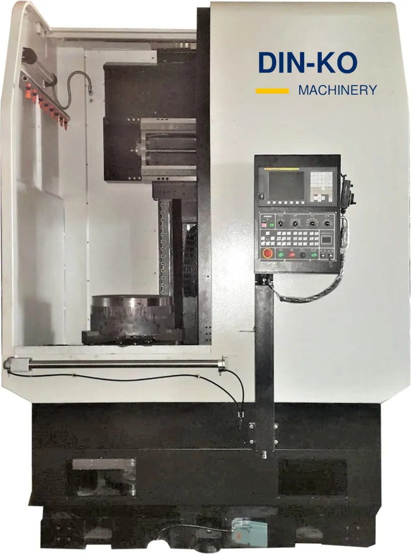
Vertical turning center
HW-650
Vertical turning platform for medium discs and rings.
- Max. turning diameter
- 700 mm
- Max. cutting height
- 700 mm
- Chuck
- 15 in
- Max. load
- 1,000 kg

PRODUCT SYSTEMS · VERTICAL TURNING
From compact disc parts to heavy, large-diameter components — vertical rigidity built for production.
The HW series covers compact to medium-size vertical turning centers; the HWL series handles large, heavy, thin-walled or irregular workpieces. HW options include live-tool turrets (P), tool magazines (M / M+CS) and twin turrets (HW-T); HWL C variants add live tools, so more operations can be completed in one setup.
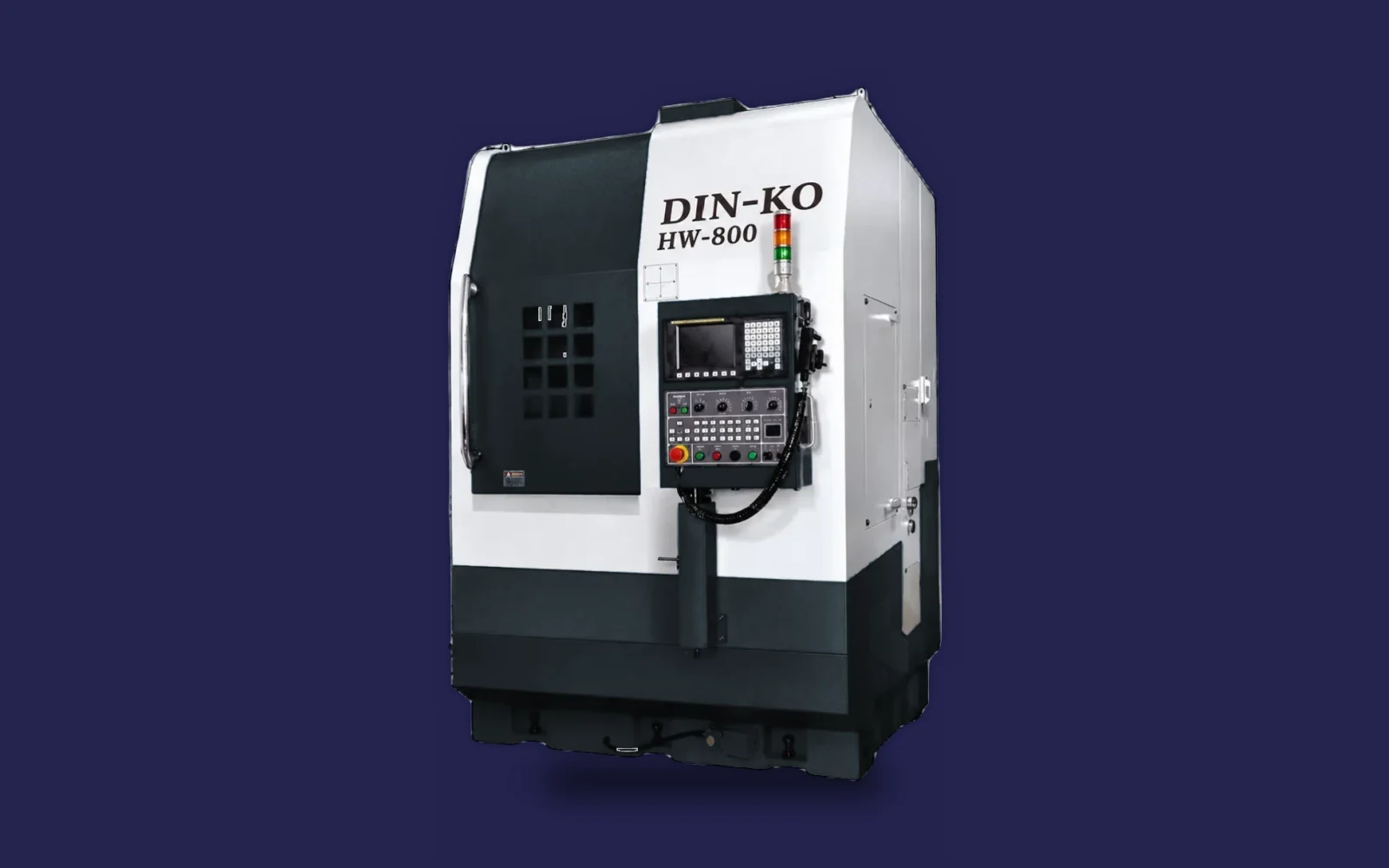
VERTICAL · RIGID · AUTOMATION-READY
WHY VERTICAL TURNING
Large, thin-walled parts distorting under their own weight on a horizontal lathe? A vertical layout lets the part sit stably on its datum.
01 · HW VERTICAL TURNING & TURN-MILLING
Compact to medium vertical turning centers for disc and ring workpieces, from HW-300 to HW-1200, with P (live-tool turret), M / M+CS (tool magazine) and twin-turret HW-T650 / T800 configurations.
01Vertical turning center
Vertical turning platform for medium discs and rings.
 02
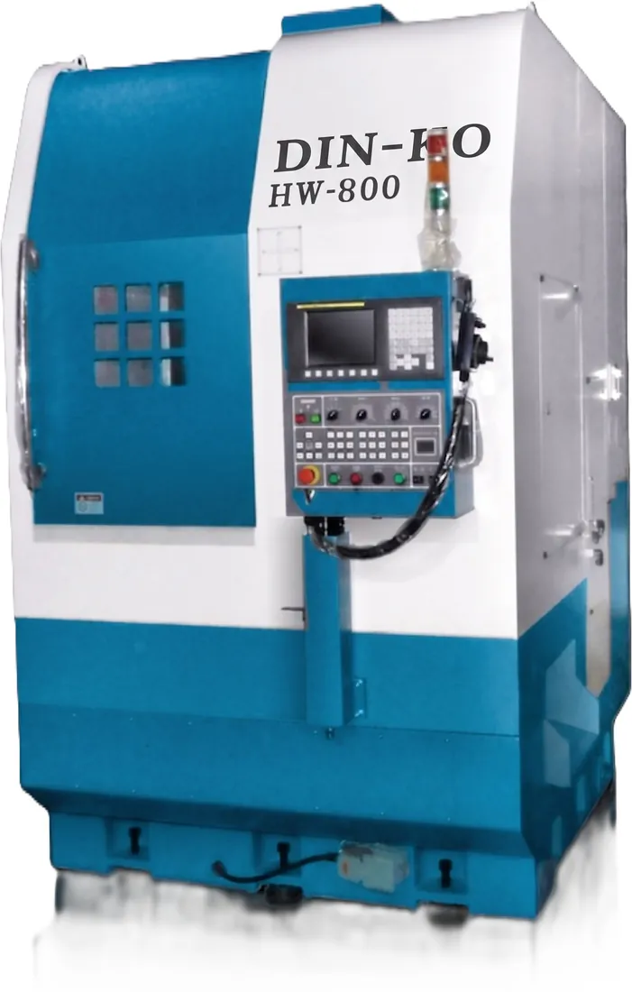
Representative model
Compact footprint, vertical workholding, enclosed machining area and front-facing CNC control for stable loading, direct operator access and efficient chip evacuation.
 03
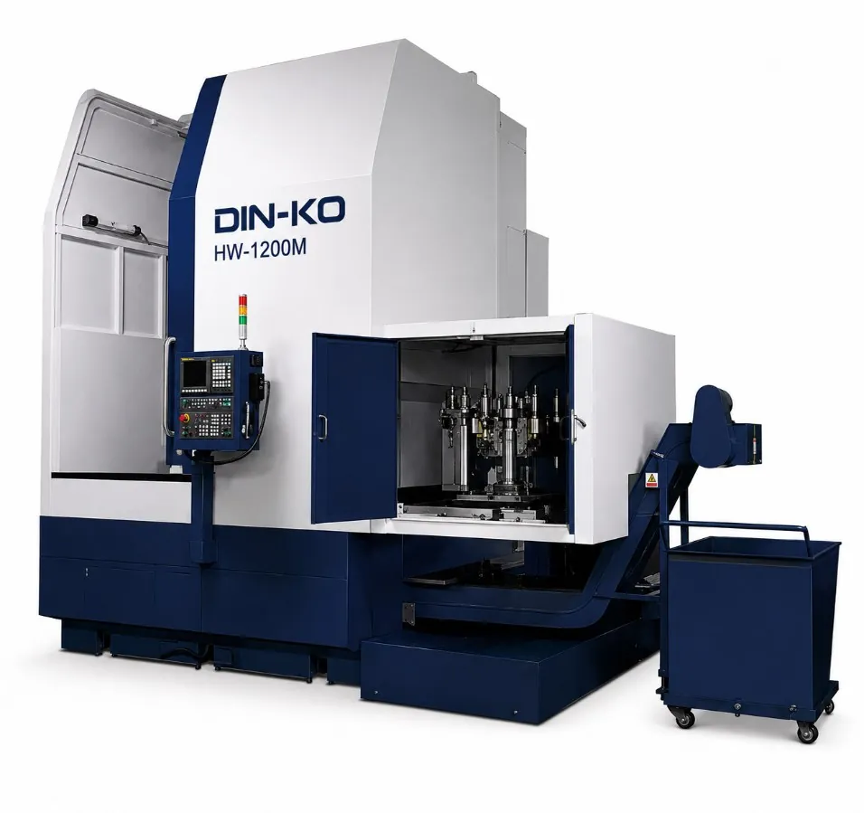
Turn-milling with tool magazine
Machining-center configuration with a BT50 tool magazine: turning, milling and drilling in one clamping.
02 · HWL LARGE VERTICAL LATHES
Large vertical lathes for heavy, thin-walled or irregular workpieces in two frame families, fixed-beam HWLF and moving-beam HWL, each in 1,000, 1,200 and 1,600 sizes, with C variants in both.
HWLF-1000 / 1200 / 1600 (and C)
Crossrail position is fixed; the ram covers the working height.
HWL-1000 / 1200 / 1600 (and C)
Crossrail travel adjusts to workpiece height.
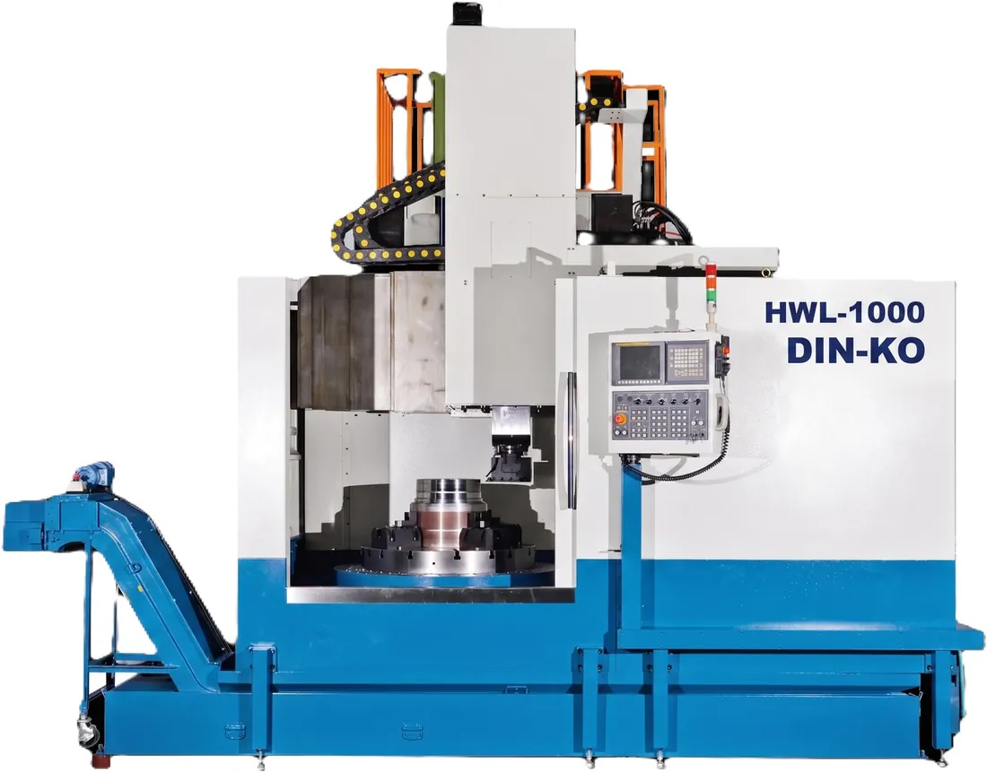 01
Moving-beam large vertical lathe
1,000 mm worktable; C variants add live tools.
CONFIGURATION
HWL standard equipment also includes an ATC tool magazine, electrical cabinet chiller, high splash guard and 7 kg/cm² coolant pump; the exact configuration is confirmed in the technical proposal.
| Model | Max. turning dia. mm | Max. cutting height mm | Chuck / table | Max. load | Spindle motor kW | Control |
|---|---|---|---|---|---|---|
| HW-300 | 350 | 300 | 8 in | 360 kg | 7.5 / 11 | FANUC 0i |
| HW-450 | 450 | 360 | 12 in | 520 kg | 11 / 15 | FANUC 0i |
| HW-500 | 500 | 450 | 15 in | 650 kg | 15 / 18.5 | FANUC 0i |
| HW-650 | 700 | 700 | 15 in | 1,000 kg | 18.5 / 22 | FANUC 0i |
| HW-800 | 800 | 800 | 21 in | 1,200 kg | 18.5 / 22 | FANUC 0i |
| HW-1000 | 1,000 | 800 | 32 in | 1,650 kg | 37 / 45 | FANUC 0i |
| HW-1100 | 1,100 | 800 | 32 in | 1,900 kg | 37 / 45 | FANUC 0i |
| HW-1200 | 1,200 | 900 | 32 in | 2,300 kg | 37 / 45 | FANUC 0i |
| HW-T650 | 650 | 700 | 13–24 in | 1,000 kg | 45 / 55 | FANUC 0i |
| HW-T800 | 800 | 850 | 16–26 in | 1,200 kg | 60 / 75 | FANUC 0i |
| HWLF / HWL-1000 | 1,100 | 900 (fixed) / 950 (moving) | Table 1,000 mm | 7 t | 37 / 45 | FANUC 0i |
| HWLF / HWL-1200 | 1,350 | 1,000 (fixed) / 1,300 (moving) | Table 1,250 mm | 9 t | 37 / 45 | FANUC 0i |
| HWLF / HWL-1600 | 1,750 | 1,000 (fixed) / 1,300 (moving) | Table 1,600 mm | 10 t | 37 / 45 | FANUC 0i |
Final specifications and scope of supply are confirmed in the technical proposal.
DIN-KO INTEGRATION
DIN-KO plans the machine, workholding, loading and measurement around your workpiece and proves it with a trial cut on the actual part, with one team from machine to validation.
ENGINEERED, BUILT AND INTEGRATED IN TAIWAN
TELL US WHAT YOU NEED TO TURN
Send the following and our engineers will recommend a model and configuration.